
Sawtooth generator circuit II

The sawtooth voltage generator circuit typically consists of a capacitor, a transistor, and resistive components that help define the charging and discharging paths. The capacitor charges through a resistor connected to the transistor's emitter, which is configured to allow a constant current to flow. The constant current source is vital for maintaining linearity in the output waveform. The transistor operates in a common base configuration, where the base is connected to a fixed voltage, allowing the emitter current to remain stable and thereby controlling the collector current.
In operation, the capacitor charges towards the supply voltage, and once it reaches a predetermined threshold, the transistor switches off, allowing the capacitor to discharge rapidly. The discharge path typically includes a resistor that defines the rate of discharge, which is crucial for establishing the waveform's frequency and duty cycle. By adjusting the values of the resistors and the capacitor, various sawtooth frequencies and amplitudes can be generated.
The circuit's performance can also be influenced by external factors such as temperature and supply voltage variations. Therefore, designing for stability and robustness is essential in practical applications. Feedback mechanisms can be incorporated to further enhance linearity and minimize distortion. Additionally, the use of precision components can significantly improve the overall performance of the sawtooth voltage generator, ensuring that it meets the specific requirements for various electronic applications.Crossing various sawtooth voltage generator, the common denominator is the use of a capacitor charge. Discharge effect to generate a sawtooth voltage of the forward and inverse process. Simple sawtooth voltage generator circuit is simple, but the output voltage linear sawtooth poor voltage amplitude changes exponentially with time, departing from the linear serious, and power efficiency is not high. To get a good linear sawtooth core voltage crossing, the key is to try to make the scan of the capacitor to maintain constant current charging within, which is the basic point of departure for a constant current source sawtooth voltage generator.
Constant is the use of flooded common base connected transistor law in emission current J. Linden Certainly, the collector current is essentially unchanged, maintaining the capacitor charging characteristics to achieve this constant stream of linear scan. But when the constant current circuit with a transistor change after the scan voltage amplitude and is saturated, the scanning voltage will not change, the output voltage waveform appears flattened, therefore, in this circuit, the output amplitude of certain restrictions the most significant v, rhn, only mound -Ut.
To make the scanning wave does not appear flattened and distorted, the best period of the scan (ie, the maximum scan cycle) 1, Li; they should charge the capacitor to the output of the transistor VT1 maximum time required for the amplitude of a million, such as circuit FIG. He was excited by the scanning of a sawtooth generator (Tp), quiescent (z,) and period (n), depending on the telogen, pulse width and period of the input signal, only generator retrace period by the circuit itself parameters decision.
Related Circuits
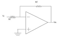
The series consists of input buffers that match the output. This configuration resembles a common collector circuit with a reinforcement factor of 1. A resistor value is included to limit the current usage. The effectiveness of this circuit largely...
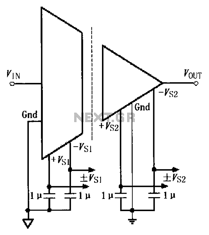
The basic connection circuit for the ISO122/124 includes power and signal connections. Each supply terminal of the ISO122/124 must be equipped with a 1 µF tantalum capacitor serving as a bypass filter. It is important to position the printed...

A school operates with a total of eight periods, each lasting 45 minutes, and includes a 30-minute lunch break following the fourth period. A bell is used to signal the start of each class, the end of each period,...
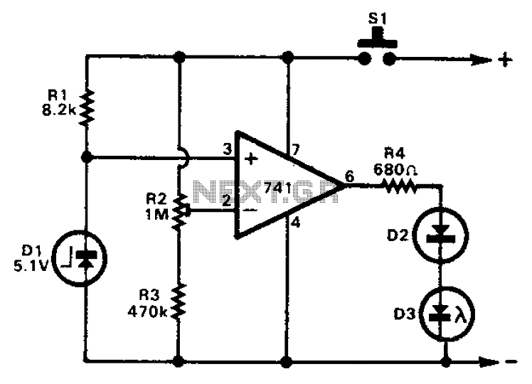
The 741 operational amplifier can function as a voltage comparator. It features a non-inverting input and a Zener-controlled voltage source, with a reference voltage set at 5.1V. Resistor R2 is used to adjust the in-phase input voltage to half...
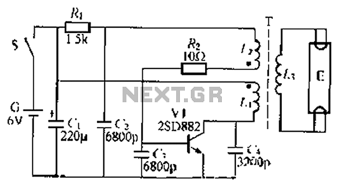
The circuit described is a battery-powered fluorescent lamp system designed for temporary emergency lighting during power outages. It utilizes a transistor (V7) and a boosting transformer (T) along with an inductive feedback oscillator to generate a high-voltage output. When...
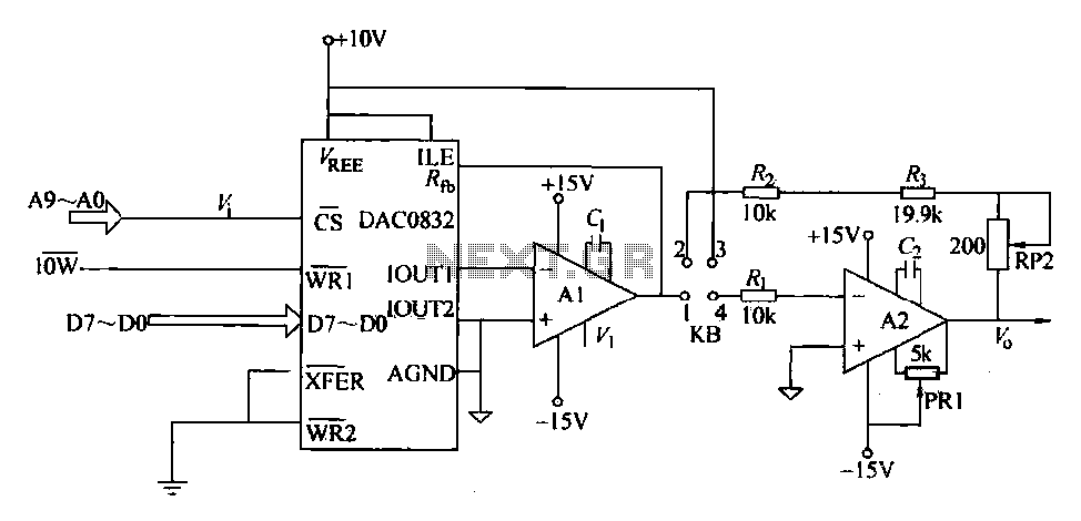
The DAC0832 is a digital-to-analog converter (DAC) chip designed for integration with computer bus systems. It features an 8-bit resolution and operates with a single power supply ranging from 5 to 15 volts. The device is compatible with TTL...