
NE555 circuit diagram of a divider circuit
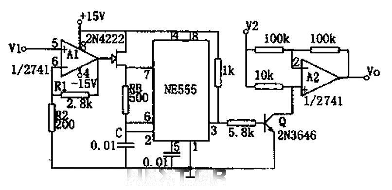
The circuit integrates a voltage-to-frequency conversion mechanism with an amplitude modulation capability, facilitating the transformation of an input voltage signal into a frequency-modulated output. The operational amplifier A1 serves a crucial role in regulating the internal resistance of the FET 2N4222, which is essential for adjusting the frequency of the astable multivibrator. This configuration allows for precise control over the oscillation frequency based on the input voltage V1.
Operational amplifier A2 is tasked with amplitude modulation, where it processes the input signal V2 to produce a modulated output. The modulation depth and characteristics can be fine-tuned by adjusting the circuit components, particularly R1 and R2, which influence the pinch-off voltage of the FET. The relationship defined by Vo - V2/V1 indicates that the output voltage Vo is directly influenced by the ratio of the input voltages, emphasizing the need for careful calibration within the specified range of 0 to 10V.
To obtain the average output voltage Vo, a filtering stage is included, which smooths out the variations in the modulated signal. This filtered output can then be accurately measured using a damped voltmeter, providing a reliable means of monitoring the circuit's performance. The design demonstrates versatility and applicability in various electronic applications, particularly in signal processing where frequency and amplitude modulation are required. As shown in FIG circuit by the voltage - frequency converter and an amplitude modulator. Input voltage V1 by the operational amplifier A1 control FET 2N4222 internal resistance , thereby changing the astable multivibrator oscillation frequency. A2 is the amplitude modulator, modulated by the input signal V2 output. Let FET pinch-off voltage Vp,Tt (1 + R1/R2) Vp, the output and input of the relationship: Vo -V2/V1 V1 and V2 required range is 0 ~ 10V. Vo is the average output can be obtained through the filter, you can also use damped voltmeter readout.
Related Circuits
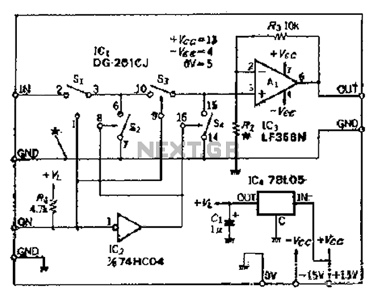
Analog switches SL and SA disconnect the inverted logic signal to terminal 2. S1 and S4 are turned on, allowing capacitance between S1 and S8 to couple. S2 and S4 shunt with an on-state resistance ranging from 50 to...
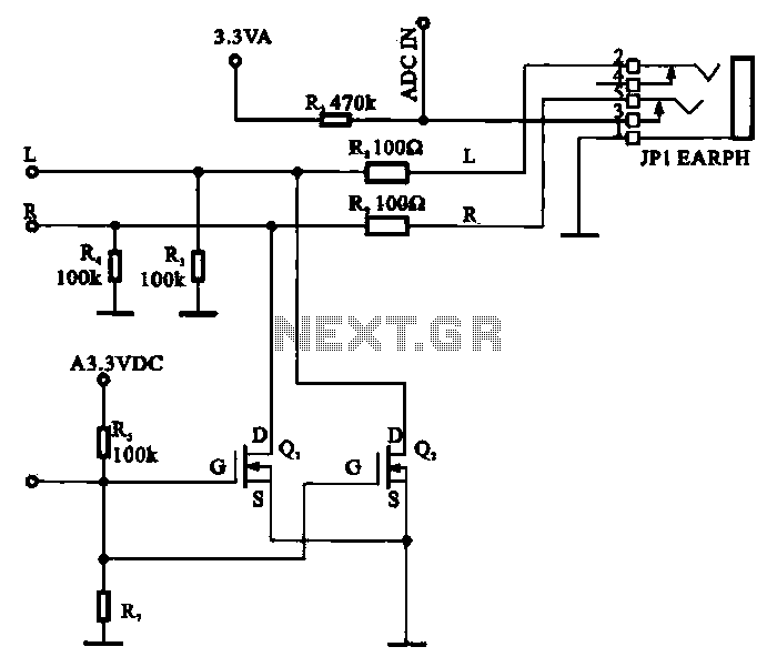
A field-effect transistor (FET) is utilized in a headphone circuit designed to function as a silencer tube. The circuit integrates L from the digital signal processing unit and R from the audio signal into the headphone jack's mute control...
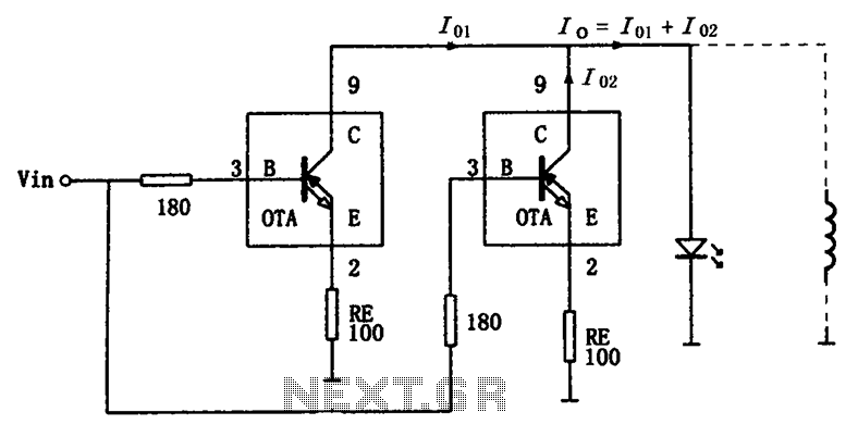
The high-speed parallel current drive circuit utilizes the OPA660 operational transconductance amplifier (OTA). An input signal, Vin, is connected to a 180-ohm resistor equivalent device at the base (pin 3) of the OPA660. The collector (pin 8) is directly...
The circuit is a DC to DC converter utilizing a standard 12 VAC center-tapped power transformer configured as a blocking oscillator. Although the circuit exhibits low efficiency, it generates a high voltage suitable for low-power applications. The input battery...
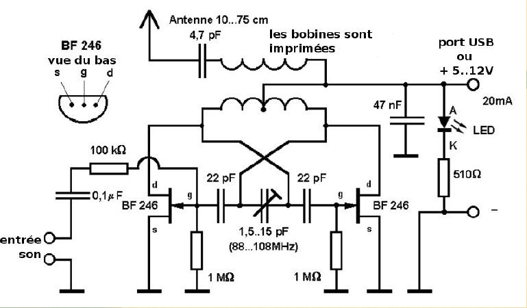
Here is a small FM transmitter circuit designed for desktop or laptop use, allowing users to enjoy movies and music from a distance. This USB-powered FM transmitter connects to a computer or MP3 player and broadcasts on a tape...
The SheevaPlug is known to have a suboptimal power supply, particularly affecting users in the UK operating at 240VAC. Additionally, heavy loads on the USB can cause issues, especially when connecting an external mechanical disk drive. This project aims...