
Triac lights automatically switch schematic
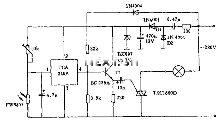
The 200W lamp switch control circuit is designed to automatically manage lighting based on ambient light intensity. The system incorporates a light-dependent resistor (LDR) or a similar photoresistor as the primary sensing element. When the light level falls below the defined threshold of 100 lux, the resistance of the LDR increases, allowing a voltage divider configuration to produce a voltage that exceeds the threshold required to activate the transistor.
The circuit employs a standard NPN transistor, which acts as a switch to control the current flow to the load, represented by the lamp. The transistor is configured to turn on when the input voltage reaches approximately 0.7V, which is the typical base-emitter turn-on voltage for silicon transistors. The emitter of the transistor is connected to the load, allowing the flow of current to energize the lamp during the low light condition.
The triac is utilized in conjunction with the transistor to handle the AC load. The gate of the triac is connected to the collector of the transistor, ensuring that when the transistor is activated, it provides a gate pulse to the triac, allowing it to conduct and power the lamp. When ambient light exceeds 100 lux, the output of the threshold switch becomes negative, cutting off the gate current to the triac, which in turn deactivates the lamp.
Power for the circuit is derived from the AC mains supply, which is rectified by diodes D1 and D2 to produce a smooth DC voltage necessary for the operation of the control circuit. The rectification process ensures that the circuit operates safely and effectively without exposure to high AC voltages. The design also incorporates filtering capacitors to stabilize the voltage and reduce ripple, ensuring reliable operation.
Overall, this circuit serves as an efficient solution for automatically controlling lighting based on environmental conditions, enhancing energy savings and convenience in various applications such as outdoor lighting, security lights, and garden illumination.200W lamp switch control, power supply voltage is 220V, is about 100lx illumination light automatically turned on or off. In the ambient light is dark time sensitive resistor w as high resistance, the voltage threshold switch input voltage of about 2 feet higher than 0.7 times, its output also showed a high resistance, so the grid voltage by dividing resistors followed by the positive half cycle transistor is turned on, and at the emitter electrode of each half cycle to form a trigger pulse, the load is energized. When strong light (more than 100lx), the threshold switch output terminal becomes negative, the transistor and the triac gate no current, the circuit fails.
Circuit required by the DC voltage obtained after rectification diodes D1 and D2. Current control circuit requires about 15mA.
Related Circuits
When the ON/OFF button is pressed once, the equipment goes on and stays on. It goes off when the button is pressed again. The circuit is straightforward. It uses a JK CMOS Flip-Flop with its JK terminals tied high...
Tired of experimenting with capacitors? It's time to explore supercapacitors, which offer significant storage capabilities. This article provides instructions on building a small LED flashlight utilizing supercapacitors. A minimum voltage of 2 volts is necessary to illuminate the LED,...

The complete hardware schematic of the Night Light Saver V6.0 includes an AC line protected by a 1A fuse (F1). Any short circuit caused by the components of the saver will blow the fuse. Resistor R1 and capacitor C1...
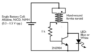
In this small switching power supply, a Schmitt trigger oscillator is used to drive a switching transistor that supplies current to a small inductor. Energy is stored in the inductor while the transistor is on, and released into the...
This is a circuit of a Clap Triggered Switch. When the circuit detects a tap, a short whistle, or a clap, it will toggle the LEDs. Resistors of 33k and 5.6k are used to charge the circuit. The Clap Triggered...
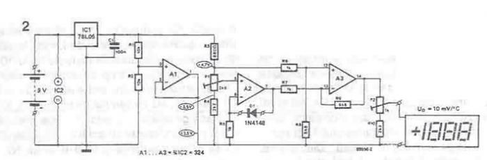
A simple thermometer can be constructed using operational amplifiers and a standard or protective diode, such as the 1N4148, as depicted in the electronic diagram below. A constant reference voltage is supplied to the non-inverting input of the operational...