
Pot plant water tester
The described device operates as a basic moisture sensor for plants, utilizing two conductive probes to detect the presence of water in the soil. The design consists of a simple circuit that includes a power source, the probes, a resistor, and an LED indicator.
The probes, which can be made from paperclips, are inserted into the soil of the pot plant. When the soil is moist, it conducts electricity between the two probes. This conductivity completes the circuit, allowing current to flow from the power source through a resistor and into the LED. The LED will light up, providing a visual indication that there is sufficient moisture in the soil.
In terms of circuit design, the power source can be a small battery, such as a 9V battery or a pair of AA batteries, depending on the desired voltage and current requirements. The resistor is crucial as it limits the current flowing through the LED to prevent damage. A typical value for this resistor could be around 220 ohms, depending on the specific LED characteristics.
To enhance the reliability of the moisture detection, it may be beneficial to implement a simple comparator circuit using an operational amplifier. This would allow for adjustable sensitivity and the ability to set a threshold for moisture detection. Additionally, incorporating a buzzer or a more sophisticated display could provide alternative indications of moisture levels, making the device more user-friendly.
Overall, this moisture sensing device is an effective and straightforward solution for monitoring the water content in potted plants, ensuring that they receive adequate hydration without the need for constant manual checks.This simple device checks if their is water in a pot plant. You stick the two probes(paperclips)into the pot plant and if the LED lights, it means there is water in the pot plant. 🔗 External reference
Related Circuits

The simple transistor tester in Figure 1 allows for the identification of the type of transistor and aids in detecting the emitter, collector, and base of the transistor. The simple transistor tester circuit is designed to facilitate the identification of...
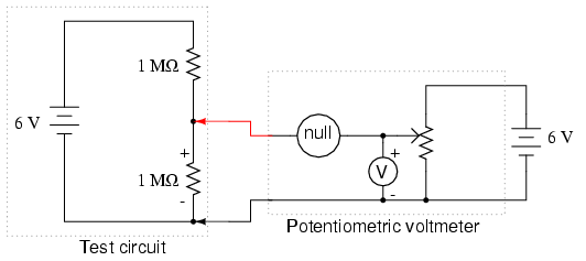
The potentiometer value is not critical; any value from 1 kΩ to 100 kΩ is acceptable. If the "precision potentiometer" described earlier in this chapter has been constructed, it is recommended for use in this experiment. The actual values...
Most telephone equipment today utilizes a DTMF receiver integrated circuit (IC). A widely used DTMF receiver IC is the Motorola MT8870, which is commonly found in electronic communication circuits. The MT8870 is an 18-pin IC employed in telephones and...
This is a simple use of the PIC 16F84 about a diode tester. Test procedure: We set "1" to PB0 and "0" to PB3. If the diode is ok and opens, then at PA0 we have "1". If PA0...
This circuit emits an intermittent beep or flashes an LED when the water level in a container reaches a predetermined height. It is designed to be mounted on top of the container, such as a plastic tank, using two...
This circuit utilizes the widely available LM3914 integrated circuit (IC), which is straightforward to operate and does not require external voltage regulators due to its built-in voltage regulator. It can be powered from various sources. When the test button...