
Precision full wave rectifier
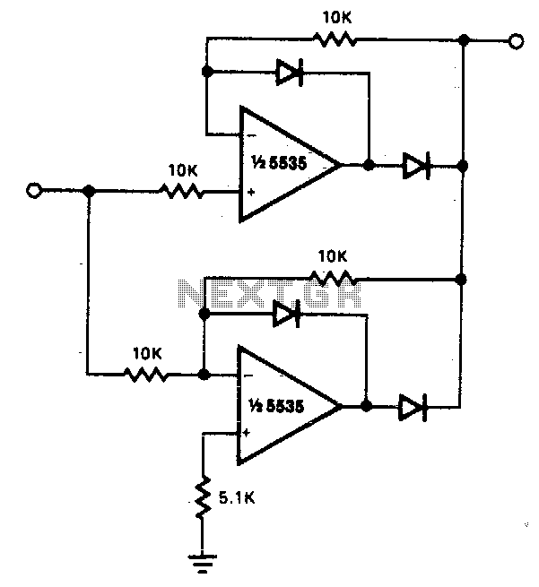
The circuit in question is designed for full-wave rectification, which is a process that converts both halves of an AC waveform into a usable DC signal. The low output impedance characteristic is advantageous as it allows for efficient power transfer to the load, minimizing voltage drop and ensuring that the rectified output maintains integrity across varying signal levels.
The inclusion of 10K resistors serves a dual purpose: they limit the current that can be drawn from the output and help stabilize the output voltage. This design consideration ensures that the circuit operates within safe parameters, preventing damage to the diodes or the connected load. The recommendation to reference the load to ground or a negative voltage is crucial to maintain proper operation and prevent erroneous readings or damage to the circuit.
The mention of diode polarity is significant in full-wave rectification. By reversing the polarity of the diodes, the output voltage will also reverse, which can be useful in certain applications where the output needs to be inverted. This characteristic allows for flexibility in circuit design, enabling the same circuit to be adapted for different requirements without extensive redesign.
Furthermore, the performance of the circuit can be influenced by the choice of operational amplifiers used in conjunction with the rectification process. The 741 operational amplifier, while widely used, has limitations, particularly regarding distortion at lower frequencies. The noted 5% distortion at 300 Hz indicates that care must be taken when selecting components for applications that require high fidelity, especially in audio or precision measurement contexts.
Overall, this circuit serves as a reliable solution for applications requiring efficient full-wave rectification, with careful consideration given to component selection and load management to ensure optimal performance.The circuit provides accurate full wave rectification. The output impedance is low for both input polarities, and the errors are small at all signal levels. Note that the output will not sink heavy current, except a small amount through the 10K resistors. Therefore, the load applied should be referenced to ground or a negative voltage. Reversal of all diode polarities will reverse the polarity of the output Since the outputs of the amplifiers must slew through two diode drops when the input polarity changes, 741 type devices give 5% distortion at about 300 Hz. 🔗 External reference
Related Circuits
When an alternating current signal is applied to a capacitor, the phase of the charging current and the voltage across the capacitor shifts by 90 degrees. Conversely, when an alternating current signal is applied to an inductor, the voltage...
A TTL counter, an 8-channel analog multiplexer, and a fourth-order low-pass filter can generate sine waves ranging from 10 kHz to 25 kHz with a total harmonic distortion (THD) better than -80 dB. The circuit employs two cascaded second-order,...
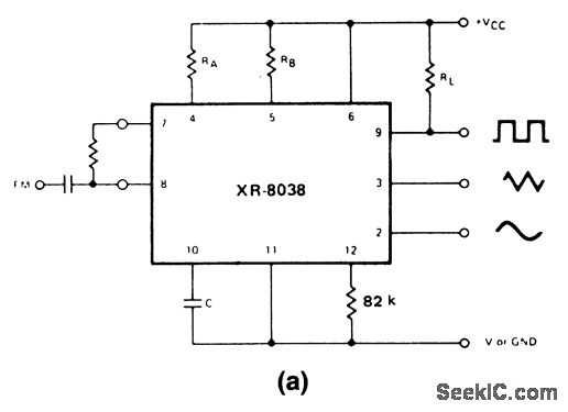
These circuits are similar to that of Fig. 5-47, except that they provide for FM or sweep modulation. Circuit 5-50A is used for FM with small deviations, approximately ±10%. Circuit 5-50B is designed for a sweep range of 1000:1....
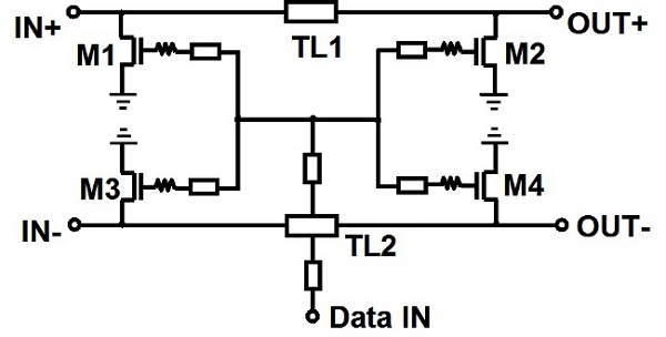
An edge combiner utilizing MOSFETs C and D is designed to generate a 16 ps pulse. The center frequency varies as a function of the NMOS width (Wser) relative to the inverter width (Winv). Figure 12 illustrates the transmitted,...
Most inverters available in the market utilize a modified sine wave to achieve better output at a competitive cost. The modified sine wave unit employs a 50% fixed PWM square wave, with the peaks balanced by a capacitor to...
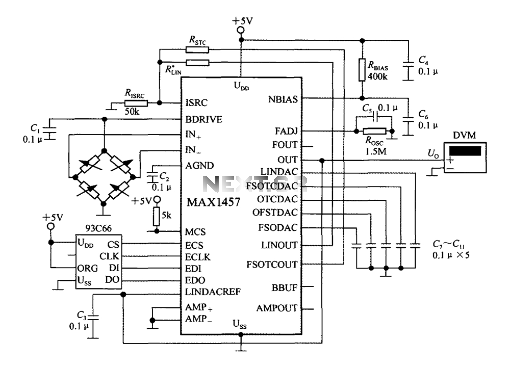
The circuit diagram illustrates a digital precision pressure tester using the MAX1457 integrated circuit with an external ROM selection of the 93C66 type, which is a 4096-bit E2PROM. Upon powering on, the MCS pin is pulled to a high...