
raspberry pi vu meter

The AD557 DAC operates with a single 5V supply, which is ideal given the readily available 5V power from the Raspberry Pi. The DAC produces an output voltage range from 0V to 2.55V, where an input value of 0 corresponds to 0V output and an input value of 255 corresponds to 2.55V output. The input voltage range for the DAC is flexible, accepting 0 to 0.8V as "0" and 2 to 5V+ as "1," making it compatible with the Raspberry Pi's 3.3V digital outputs. Various GPIO pins on the Raspberry Pi provide a number between 0 and 255 to the data input pins (1 through 7) on the DAC. The DAC is powered and grounded using the 5V power and ground pins available on the Raspberry Pi GPIO header.
The DAC features three Vout pins, which may seem unusual but allow for alternative configurations for non-standard output voltage ranges. The CS (chip select) and CE (chip enable) pins on the AD557 are important for controlling the output voltage. The output voltage changes only when both pins are low (grounded), ensuring that the right values are set on the data pins before updating the output voltage, thus preventing unintended changes. In this setup, the CS pin is permanently connected to ground, while the CE pin is connected to a GPIO pin for software control. The CE pin must be driven from high to low for at least 225ns to update the DAC output voltage.
A 15K resistor is included in the circuit to limit current. The Sifam audio level meter used in this project is current-driven and requires minimal current. It indicates a reading of 0 (entering the red zone) at approximately 300µA. At the maximum DAC output voltage of 5V, the 15K resistor ensures the meter receives around 333µA (5V / 15,000Ω), placing the needle appropriately into the red zone. It is important to note that while this meter is labeled as a VU meter, it does not provide a true VU reading, as the VU standard has a strict definition that is not being emulated in this project.
The circuit will be soldered and housed in a suitable enclosure for final assembly.I have been working on driving an analog VU meter based on the sound going out the Raspberry Pi`s audio outputs. This now works! The music [1] is playing from a Raspberry Pi, with software running on the Pi digitally sampling the peak output audio level and writing that out to an 8-bit digi
tal-to-analog converter (DAC). The DAC output is then used to drive the analog meter. If you`re interesting in knowing how all this hangs together, keep reading. The Raspberry Pi is very capable of generating digital signals using its GPIO pins but an analog meter requires an analog signal. To convert a digital value emitted from the Raspberry Pi to an analog voltage we need a DAC. It`s possible, and rewarding, to build a DAC using discrete components, but it`s more convenient, accurate and reliable if you use an off-the-shelf DAC packaged as an integrated circuit (IC).
5V single supply operation: The AD557 requires just a single 5V supply voltage. This is ideal for the Raspberry Pi where we have 5V power readily available. Many DAC ICs require a supply voltage somewhat higher than 5V making them trickier to use with the Pi. 0 to 2. 55V output: A value of 0 at the input gives 0V at the output. A value of 255 at the input (the maximum) gives 2. 55V at the output. This is easy to work with and think about. Flexible input voltage: The digital inputs accept values of 0 to 0. 8V as "0", and 2 to 5V+ as "1", making them compatible with the 3. 3V digital outputs on the Raspberry Pi. Various GPIO pins on the Raspberry Pi are used to provide a number between 0 and 255 to the data input pins (1 through 7) on the DAC.
The power supply and ground for the DAC are provided by the 5V power and ground pins available on the Raspberry Pi GPIO header. The slightly odd seeming output configuration involving three Vout pins is actually just what is required for normal operation.
These three pins allow for alternate configurations where a non-standard output voltage range is required. See the AD577 documentation for more details. The CS (chip select) and CE (chip enable) pins on the AD557 warrant some explanation. The DAC will only change its output voltage when both of these pins are low (at ground). This means that you can ensure you have the right values set on the data pins before telling the AD557 to update the output to the next value, ensuring unintended changes in output voltage are avoided while a new value is being set on the inputs.
There are use cases that require both the CS and CE pins to be used which I won`t go in to here. Since we only need one of these pins here, CS is connected permanently to ground. CE is connected to a GPIO pin so we can control it from software running on the Raspberry Pi. The value on CE pin needs to be dropped from 1 to ground 0 for at least 225ns in order for the AD557 to update it`s output voltage to a new value. The 15K resistor is there to limit current. The Sifam audio level meter we`re using is current driven, and needs very little current at that. It will show 0 (where the meter goes in to the red) at around 300uA. At the maximum output voltage from the DAC (5V), a 15K resistor will ensure the meter gets around 333uA (5 / 15000) which puts the needle nicely just in to the red zone.
Note that although this meter is marked as a VU meter, we are in no way indicating a true VU reading. The VU term has a strict definition which we`re not trying to emulate in any real way here. I hope you`ve found this post interesting and/or educational. My wife and I are about to solder up the circuit and get it and the Pi in to some kind of box. I`ll certainly post some pictures of the result once that`s done. 🔗 External reference
Related Circuits

Most analog multimeters can measure resistance across a wide range of values; however, they can be inconvenient due to their reverse reading scale, which is also non-linear. This can lead to poor accuracy, especially at the high-value end of...
This article discusses the creation of a digital thermometer using the Arduino Uno. The temperature sensor employed is the LM35DZ, although it can be substituted with other sensors like the DS18B20. The sensor detects temperature and sends the data...
The Kill A Watt is a product that measures volts, amps, and power factor of individual appliances, allowing users to calculate power consumption and running costs. However, a desire for a solution that provides similar data for an entire...
This LC meter circuit is capable of measuring inductors and capacitors. When either Lx or Cx is connected to the circuit, the oscillator frequency decreases, and this reduction is measured by a frequency-voltage converter constructed with transistors T3 and...
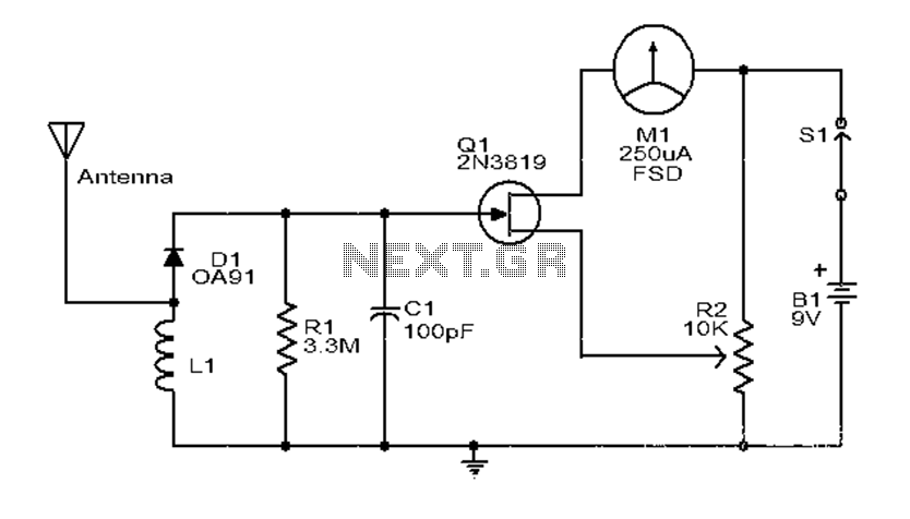
This is a simple and low-cost broadband high-frequency electric field strength meter. The field strength of the radio signal is converted into a DC measurement for analysis. The signal is captured by a coil and processed through a diode...
This sound level measuring device circuit can be used to control the intensity of a sound recording in the field of a disco. It has five measurement ranges between 70 and 120 dB, with a measurement accuracy of 0.5...