
Touch triggered bistable
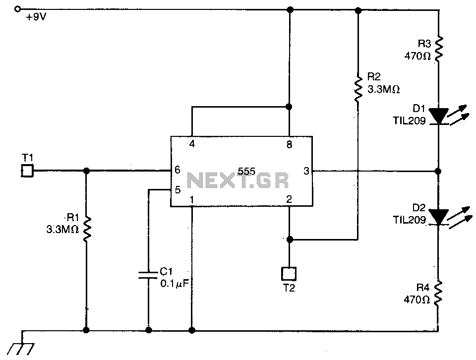
The described circuit utilizes a 555 timer in bistable mode, which is a versatile configuration often used for toggle switches or memory elements. In this mode, the timer can maintain its state until triggered by an external input. The circuit features two touch-sensitive terminals, T1 and T2, which serve as activation points for the timer.
When T2 is touched, it triggers the 555 timer, resulting in a high output signal from pin 3. This signal allows current to flow through diode D2, which illuminates it while simultaneously cutting off current to diode D1, effectively extinguishing it. This visual feedback is critical for users to understand the current state of the circuit.
On the other hand, touching T1 triggers the timer to produce a low output. This action allows current to flow through D1, lighting it up, while D2 is turned off. The ability to toggle between these two states provides a simple yet effective way to control other devices, such as a triac that can manage a lamp or other inductive loads.
The circuit design includes LEDs, which serve a dual purpose: they not only indicate the state of the output but also help users identify the touch terminals in dark environments, enhancing usability.
Capacitor C1, while not essential, can be incorporated to improve the circuit's resilience against false triggering caused by noise or spurious pulses. This is particularly useful in environments with electrical interference, ensuring that the circuit only responds to deliberate touches on the terminals.
Overall, this circuit exemplifies an efficient use of a 555 timer in a bistable configuration, providing a practical solution for touch-sensitive applications with the added benefit of visual indicators.This circuit uses a 555 timer in the bistable mode. Touching T2 causes the output to go high; D2 conducts and D1 extinguishes. Touching T1 causes the output to go low; D1 conducts and D2 is cut off. The output from pin 3 can also be used to operate other circuits ( a triac controlled lamp). In this case, the LEDs are useful for finding the touch terminals in the dark Cl is not absolutely necessary but helps to prevent triggering from spurious pulses. 🔗 External reference
Related Circuits

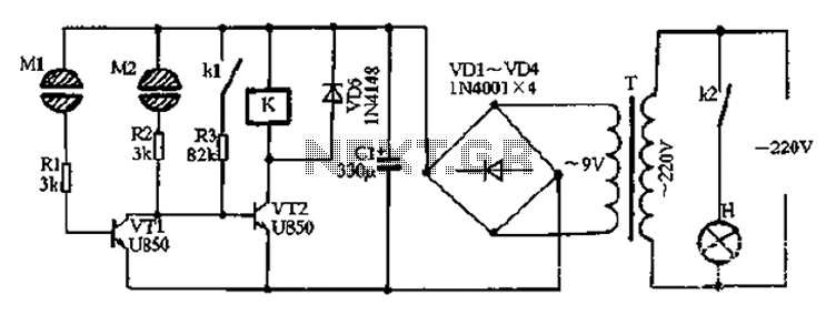
Utilize the call sheet to touch the electrical threshold M, which causes the E lamp to light up. When the same interval subparagraph is triggered, the lights will automatically turn off. A voltage regulator rectifier circuit is formed using...
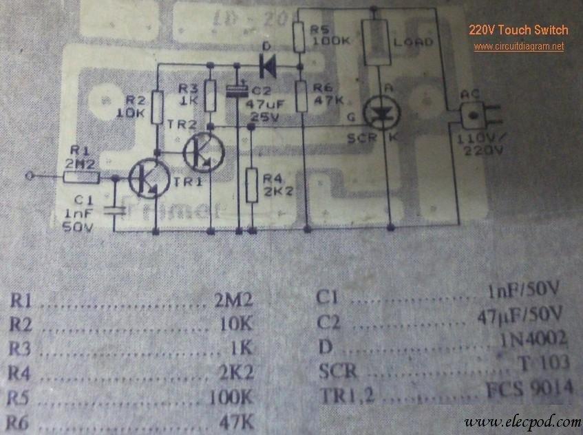
This circuit is connected directly to a 220V home electrical installation. The LOAD in the schematic diagram above represents an electronic device that consumes 220V AC current. The circuit operates by interfacing directly with the 220V AC mains supply, which...
After the power is turned on, 220V AC is stepped down by transformer T. The output is then rectified by the VD1 to VD4 bridge rectifier and filtered by C1 to produce approximately 10V DC voltage for the Darlington...
This electronic circuit utilizes a 555 timer as the foundation for a touch switch. When the plate is touched, the 555 timer is activated, causing the output on pin 3 to go high, which turns on the LED and...
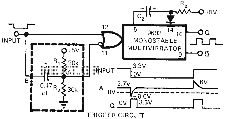
The 9602 multivibrator circuit can trigger either the rising edge or the falling edge of a square wave, but not both simultaneously. To enable double-edge triggering, two additional resistors and a capacitor can be employed. When the input signal...

This is a door knob touch alarm designed for home security purposes. The alarm is activated when someone touches the metal door knob. However, this circuit will not function on a fully metal door. The door knob touch alarm circuit...
Warning: include(partials/cookie-banner.php): Failed to open stream: Permission denied in /var/www/html/nextgr/view-circuit.php on line 713
Warning: include(): Failed opening 'partials/cookie-banner.php' for inclusion (include_path='.:/usr/share/php') in /var/www/html/nextgr/view-circuit.php on line 713