
Traffic Light Controller
The traffic light controller circuit is designed to simulate the operation of real traffic lights, providing a practical learning tool for children. The use of IC 555 timers allows for precise control of the timing intervals for each light, ensuring that the sequence accurately reflects real-world traffic light operations. The inclusion of relays enables the high-voltage light bulbs to be controlled safely, isolating low-voltage control circuitry from high-voltage components.
The design also emphasizes safety and durability, particularly in the enclosure and mounting of components. The use of a plywood plate for mounting ensures stability, while the aluminum tubes provide a robust structure for the light bulbs. The gelatine papers used to filter the light add an aesthetic element while serving the functional purpose of color differentiation.
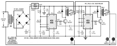
Overall, this circuit not only serves as an educational tool but also provides insights into basic electronic principles, including power regulation, timing circuits, and relay operation. It can be an effective project for hobbyists and educators looking to introduce fundamental electronics and safety concepts to young learners.Here the simple traffic light controller which is could be used to educate kids rudiments of traffic light guidelines. The circuit utilizes easily available electronic parts. It generally consists of rectifier diodes (1N4001), a 5V regulator 7805, two timers circuit using IC 555, two relays (5V, single-changeover), three 15W, 230V light bulbs and
also several discrete parts. Mains electrical power is stepped down by transformer X1 to provide a secondary output voltage of 9V, 300 mA AC. Then the transformer output current is rectified by a full-wave bridge rectifier composed of diodes D1 through D4, filtered by capacitor C1 and also regulated by IC 7805 (IC1).
IC2 is wired as a multivibrator with on` and off` periods of about 30 seconds each with the part values determined. Once mains power switch is turned on, pin 3 of IC2 goes high for 30 seconds. This, in turn, energises relay RL1 via transistor T1 and the red bulb (B1) glows through its normally-open (N/O) contact.
At the same time, mains power is turned off from the pole of relay RL2. As the on` time of IC2 ends, a triggers IC3 through C5. IC3 is set up as a monostable with on` time of about 4 seconds, which indicates pin 3 of IC3 will stay high for this period of time and energise relay RL2 through driver transistor T2. The amber bulb (B2) thus lightings up for 4 seconds. Immediately after 4-second time period of timer IC3 at pin 3 lapses, relay RL2 de-energises and also the green bulb (B3) lights up for the rest of off` period of IC2, which is about 26 seconds.
The green bulb is turned on through the normally closed (N/C) contacts of relay RL2. So when mains electrical switch is turned on, red light will light up for 30 seconds, amber for 4 seconds and green for 26 seconds. You can easily build this circuit on a general purpose PCB and enclose in a protected box. The box needs to have sufficient area for installing transformer X1 and also two relays. It could be installed near 230V AC, 50Hz power supply or mounted on the PVC tube applied in assembly of the traffic light box.
A stout cardboard box of 30x15x10cm3 is needed for housing the lights. To make certain durability, work with a 10x45cm2 plywood plate having 1. 5 centimeters thickness and also secure onto it three light outlets and the box utilizing nuts and bolts or screws. Make three tubes of thin aluminium sheet, which is easily offered in equipment stores. The inner diameter of aluminium tubes ought to be such that these can well match on the light outlets.
Working with a sharp knife, make holes opposite the outlets carefully. Wire the outlets at the back and take the cables out through the PVC tube. To begin with, fix three 15W light bulbs (B1 through B3) and then press on the tubes. Support the other ends of the tubes in the holes made on the front panel of cardboard box. Sandwich gelatine papers of the three colors in between two sheets of cardboard and fix over the tubes. The visibility of red, amber and also green lights enhances with their installation on the tubular shape.
🔗 External reference
Related Circuits
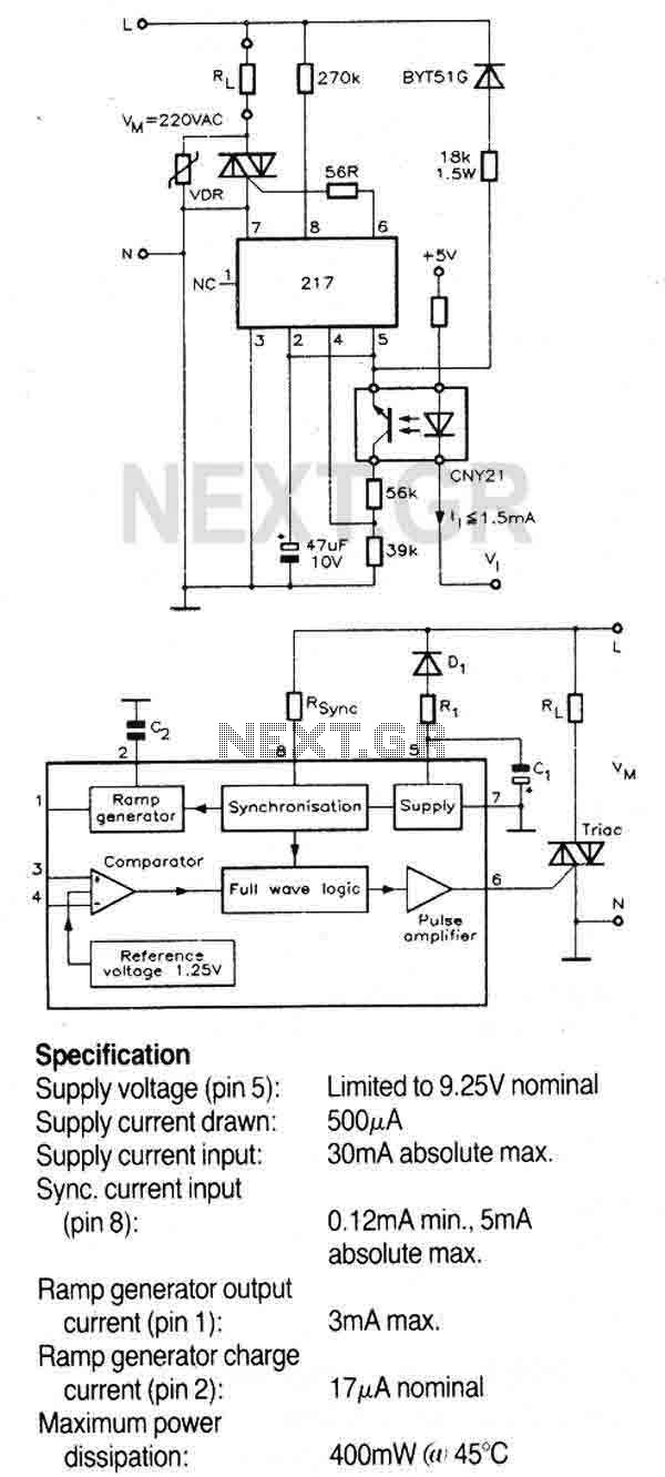
A triac controller for switching resistive loads directly from the mains supply using the zero crossing technique. The device is powered directly from the mains via a diode and dropper resistor, and the IC has its own regulator to...

When connecting this element in a voltage divider configuration, a high and low signal can be generated based on the amount of light detected by the sensor. An NPN transistor configured as an inverter further filters this signal to...
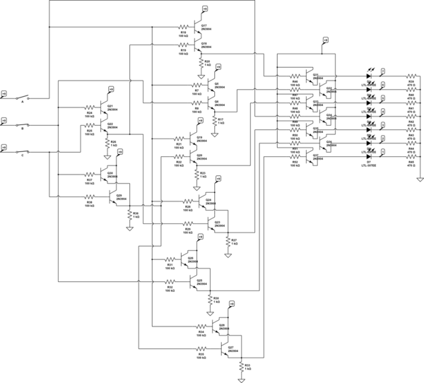
There are three switches that represent a binary number, and according to the combination of those switches, the number of lit LEDs changes to represent that binary number. There is a question regarding how to provide equal current and...
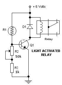
This light-dark switch activated relay circuit schematic represents one of the simplest electronic circuits designed to activate other electronic devices based on light or darkness. It requires a single electronic relay and a few common components that are not...
The following circuit illustrates an LM358 IC Solar Controller Circuit Diagram. Features include its application in mobile communications base stations and conversion capabilities. The LM358 IC Solar Controller Circuit utilizes the operational amplifier LM358 to regulate and manage solar energy....
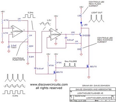
The aboriginal accessory forms a typical oscillator circuit that produces both a triangle waveform signal and a square wave signal. The triangle signal is fed into a voltage regulator circuit, which converts the triangle voltage signal to a triangle...