
Tripath Board tc2000+tp2050
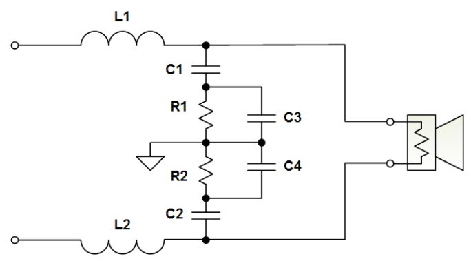
The circuit in question pertains to audio amplification, utilizing a topology that aligns with the specifications outlined in the Tripath datasheet. This suggests that the measurement reflects actual performance metrics of an operational amplifier or a class-D amplifier, which are common in high-efficiency audio applications.
The circuit likely consists of key components such as input capacitors, feedback resistors, and output transistors, structured to minimize distortion and optimize power efficiency. The topology may include a differential input stage, which is crucial for rejecting noise and enhancing signal integrity. Additionally, the use of a PWM (Pulse Width Modulation) technique may be present, allowing for efficient power conversion and amplification.
In terms of measurement, parameters such as gain, frequency response, total harmonic distortion (THD), and signal-to-noise ratio (SNR) would be critical to evaluate the performance of the circuit. The real measurement indicates that the data reflects practical performance, which can differ from simulated results due to real-world factors such as component tolerances, thermal effects, and layout considerations.
The implications of using a topology similar to that of the Tripath datasheet suggest a focus on high fidelity and low power consumption, making it suitable for portable audio devices and high-quality audio systems. Understanding the nuances of this circuit design can lead to improved performance in various audio applications.Originally Posted by Neil Davis It`s not a sim. It`s a real measurement from a circuit that has basically the same topology as the Tripath data sheet. .. 🔗 External reference
Related Circuits
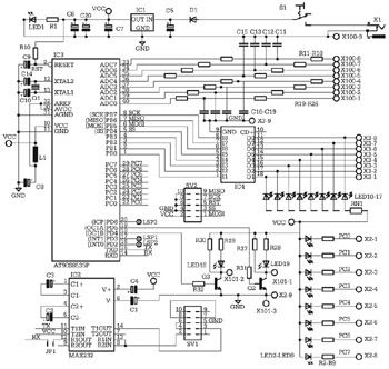
The microcontroller is an AT90S8535-P in a DIP40 package. It is pin-compatible with other members of the AVR analog series, such as the ATMega8535 and ATMega16, although there are significant differences among them. It is advisable to consult the...
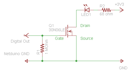
The process of driving an LED involves using a Power MOSFET to control the LED's state (On and Off) via a digital signal. This guide provides a step-by-step approach to wiring the circuit on a breadboard, which serves as...
This article discusses the utilization of old PCs as simple controllers. Many obsolete systems, such as the 8088, 8086, 80286, 80386, and 80486, are no longer capable of running modern software, yet they can still function effectively. Often, individuals...
The layout control motherboard is designed to facilitate the management of various sections of a layout. It features a microcontroller that connects to the MRNet bus and multiple slots for inexpensive control and sensor boards. All control and sensor...
This board is designed specifically to control the 5-motor Robot Arm sold by Baycom Technologies. It has no input facilities, but it is less expensive than combining the I/O Board with the Relay sub-Board. If you need lots of...
The doorbell button was replaced with a lighted version, but the chime continued to sound after the button was pressed. These lighted buttons incorporate an incandescent bulb in parallel with the button, a component that has been modified in...
Warning: include(partials/cookie-banner.php): Failed to open stream: Permission denied in /var/www/html/nextgr/view-circuit.php on line 713
Warning: include(): Failed opening 'partials/cookie-banner.php' for inclusion (include_path='.:/usr/share/php') in /var/www/html/nextgr/view-circuit.php on line 713