
Voice Shield for Arduino
The implementation of the Arduino voice shield involves a careful design that integrates various components for optimal performance. The ISD1790PY chip serves as the core of the system, handling both recording and playback functionalities. The microphone input is crucial for capturing audio, and the AGC ensures that audio levels are consistent, improving the quality of recordings. The output stages are designed to drive an 8-ohm speaker effectively, with the power bridge stage providing sufficient amplification while maintaining isolation between the digital and analog circuits.
The SPI interface simplifies communication between the Arduino and the ISD1790PY, allowing for precise control over the speech synthesis process. This includes the ability to navigate through recorded messages and manage memory efficiently. The use of manual control buttons enhances user interaction, providing a straightforward method for initiating recordings and playback. The design also accommodates external audio input, broadening the application potential of the shield.
Power management is a critical aspect of the design, with separate power lines for analog and digital sections to minimize noise and interference. The careful selection of filter capacitors ensures that the power supply is stable, contributing to the overall reliability of the device. The implementation of distinct ground paths for different sections of the circuit further aids in reducing noise, enhancing the performance of both the recording and playback functions.
In summary, the Arduino voice shield utilizing the ISD1790PY chip is a versatile platform for developing various voice-related applications. Its design emphasizes ease of use, flexibility, and high-quality audio processing capabilities, making it a valuable tool for hobbyists and professionals alike in the realm of audio electronics.The objective of this project is to build an Arduino voice shield to empower thousands of voice related applications! All this mostly thanks to an integrated ISD1790PY chip. This particular voice/ TTS feature can be useful to integrate voice messages in alarm systems, to implement generic I/O controls in home automation or even in home security ap
plications: something like playing an alert when a person or a vehicle approaches any given protected area. The use cases are many and limited only by your imagination! While this shield can operate stand-alone, it can be better managed through and SPI interface: by connecting this with Arduino it can take control of the speech synthesis.
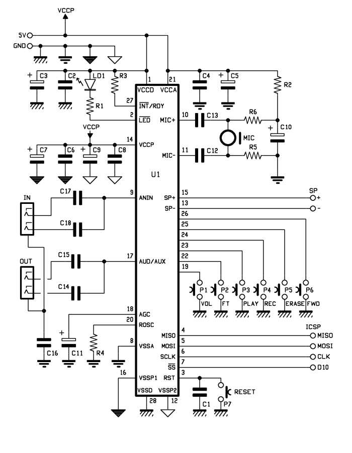
The ISD1790PY sports a microphone input with automatic gain control (AGC), an output for 8 ohms speaker and another analog output that can be configured to drive an external amplifier. Volume control features as well as anti-aliasing and smoothing filter are provided and the vAlert (voiceAlert) function is used to indicate a new message is available in memory ISD1790PY provides aso four sound effects to confirm operations such as start recording, stop recording, delete, forward and memory reset, along with vAlert, the effects are played from the AUD / AUX output.
The speaker output is amplified by a built-in power bridge stage, whose power is separated from those of both the analog section (microphone input with AGC, analog not amplified output) and digital section (sampler, memory) and is taken from the Vccp and Vssp1/Vssp2 pins. FWD allows if memory contains several messages to jump from one to another (in this case, pressing P5 deletes only following messages: in other words, if we have recorded 5 messages and we press FWD to move to the third one, by pressing ERASE we`ll delete the memory area from that point until the beginning of the fourth message, which means the third track) While ISD1790PY allows both recording the entire memory or divide the space into partitions (each defined by a specific address), addressing can only be done by SPI by adding to the command to desired address.
With manual control buttons you have to handle the P4 button: recording starts by pressing the button: it stops releasing it. Imagine that memory is empty: pressing REC I can start recording, releasing it, recording stops and ISD1790PY adds a marker in the corresponding memory location.
This marker will then be used when playing as EOM = End Of Message. When hitting the PLAY button, reading starts from the last EOM marker and stops at the next. Message logging is carried out directly with a microphone capsule (MIC) connected to the appropriate U1`s differential input (MIC+ & MIC-) via the two decoupling capacitors (from bias network and by ground), polarized by the R2, R6, R5 network. The IN audio line (that`s why a female stereo jack has been realized, whose L and R contacts end on the same U1 pin thanks to C17 and C18 capacitors) can be useful if you want to record from an external source.
Recording time is determined by the clock frequency of ISD1790PY internal oscillator, which marks the sampling; such sampling frequency is defined by the value of the R4 resistor, in this case is 8 kHz. The entire shield takes the power supply from Arduino 5V and GND pins. The three power lines (analog, digital, power) are cross-linked to Arduino`s 5V, close to the filter capacitors.
The three grounds (one for the analog section, one for the digital and one for the loudspeaker amplifier) are indicated with different symbols on the circuit diagram and joined after the filtration operated by capacitors C4 and C5 (analog), C2 and C3 (digital) and C6, C7, C8, C9 (power). Together they are joined to the pin that leads to the Arduino GND. #include
🔗 External reference
Related Circuits
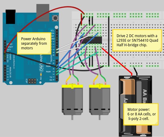
Motor shields functioned effectively; however, they are priced around $50 each, which is more than the cost of the Arduino itself. While this is acceptable for a single unit, it presents a challenge for an Arduino workshop aimed at...
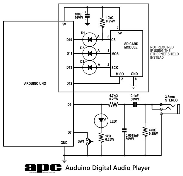
In this series, a diverse exploration of how Arduino interacts with various real-world devices has been presented, from servo motors to ultrasonic range finders, TVs to humidity sensors. The focus now shifts to generating sound using Arduino. The project...
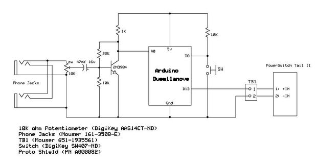
Have you ever wanted your home entertainment or sound system to power on automatically when plugging in your iPod or another portable MP3 player? To achieve automatic power activation of a home entertainment system when a portable device is...
A 5V power supply is used to function as a switch controlled by an Arduino. Direct control from the Arduino pin is not feasible because most general-purpose relays require a minimum of 150mW to activate, which translates to over...
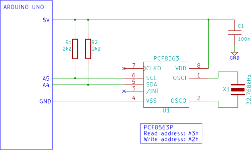
The Arduino displays the time and date on an optional LCD and in the Arduino IDE serial monitor window. A PCF8563 real-time clock (RTC) integrated circuit (IC) is utilized to generate the time and date. The time and date...
The objective of this project is to consolidate various robot designs and transform them into a new device featuring updated hardware and standardized software, specifically utilizing Arduino for ease of use. These robots share three key components: a mechanical...