
Wireless Doorbell

The schematic for this doorbell circuit can be visualized as follows: The power supply feeds into the positive rail, where the choke is placed to filter and stabilize the current. The tank circuit, comprising the coil and capacitors, is strategically designed to resonate at 303 MHz, allowing efficient energy transfer and radiation. The transistors are arranged in a configuration that facilitates signal amplification and feedback control, ensuring that the oscillations are sustained and stable. The use of a crystal in the circuit serves to enhance frequency stability, contributing to the overall performance of the transmitter. The careful selection of resistor values ensures that the transistors operate within their optimal ranges, allowing for rapid switching and minimal delay in signal transmission. The design illustrates the principles of RF circuit design, including the importance of component placement, resonant frequency tuning, and the interaction between passive and active components in generating a reliable wireless signal.The doorbell operates on the 303MHz band and the 30 metre range (100ft) is obtained without the use of an antenna! The circuit is actually radiating from the printed track of the tank circuit. The Tank Circuit is a single-turn coil and a small capacitor (5p & 4p in parallel). The circuit has been kept near the power rails by the use of a choke in the positive rail. The positive rail is then reflected to the negative rail via the battery. A 7cm length of tinned copper wire is connected to the collector of the transistor and bent around the board so that everything can be put back into the case. When the transmitter was taken outside, the range was over 60 metres (200ft) and the full range could not be tested as the sound from the doorbell was too faint to be heard!
The 303MHz oscillator consists of a self-oscillating circuit made up of the coil on the PC board and a 9p (9 puff) capacitor (actually 4p and 5p in parallel). The circuit starts-up by the transistor producing noise. This rising-and-falling signal on the collector is passed to the parallel tuned circuit (the tank circuit) and the base sees a very smooth sinewave at a frequency of 303MHz.
This current passes through the choke and the turns produce a back-emf or back voltage that fights against the flow (change) in current. The end effect is a voltage created at the point where the choke is connected to the track-work on the board.
This effectively allows the track work to produce a waveform and since the frequency of this wave is very high, a percentage of the energy is radiated into the air as electromagnetic energy. The choke allows the track-work to effectively rise and fall while providing a very low resistance path for the flow of current during certain parts of the cycle.
When the crystal is added, the frequency increases (because the effect of the 2n2 and crystal in series creates a lower capacitance than 2n2) and as it rises, the amplitude of the feedback signal increases until it reaches a maximum at the resonant frequency of the crystal. The crystal exhibits the lowest impedance (the highest capacitance) at the resonant frequency. This is how the circuit stabilizes at the frequency of the crystal. The third transistor is not fully turned on and it produces a small amount of noise. This noise is passed to the second transistor and appears on the collector. The collector passes this noise to the base of the third transistor and the noise very rapidly increases to a maximum.
When the middle transistor changes from an OFF state to an ON state, the capacitor will be partially charged and the voltage on the end connected to the base of the third transistor will drop about 6v and put a negative voltage on the base of the third transistor. This will keep it off and the middle transistor will be kept ON via the 150k base-resistor. The capacitor will gradually charge in the opposite direction via the 220k and 150k and when the base of the third transistor sees about 0.
6v, it begins to turn ON. This causes the middle transistor to turn OFF and the collector voltage rises. This causes the capacitor to charge and create a current-flow in the base of the third transistor. Both transistors are now turned ON and the capacitor charges very quickly via the 12k and base-emitter junction of the third transistor. This creates the very narrow high-period in the waveform. The 303MHz oscillator is firstly set into operation by the noise produced by the transistor and this is passed to the tank circuit made up of the 2-turn coil and 2p capacitor as a parallel tuned circuit.
The transistor keeps amplifying this until it gets to a stabilized point where the collector is producing "hash" (junk) of about 300mV. When the transmitter is activated, the receiver circuit will detect a signal as small as a few micro-volts and the 32kHz signal will be included with all the other noise.
The stage is actually a transmitter, but we w 🔗 External reference
Related Circuits
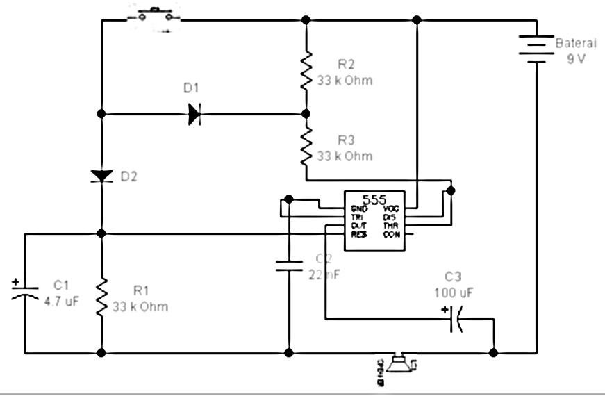
All components are arranged as depicted in the sequence below. Current will flow from the source voltage to the switch. When the switch is closed, current will flow through the diode, which acts as a closed switch due to...
Warning: Missing argument 2 for wpdb::prepare(), called in /home3/nithish/public_html/btechzone.com/wp-content/plugins/sharebar/sharebar.php on line 112 and defined in /home3/nithish/public_html/btechzone.com/wp-includes/wp-db.php on line 992 Warning: Missing argument 2 for wpdb::prepare(), called in /home3/nithish/public_html/btechzone.com/wp-content/plugins/sharebar/sharebar.php on line 124 and defined in /home3/nithish/public_html/btechzone.com/wp-includes/wp-db.php on line 992 This...
This low-cost project enables audio reproduction from a television without disturbing others. It eliminates the need for wired connections between the TV and loudspeakers. Instead, it utilizes invisible infrared light to transmit audio signals from the TV to the...
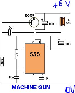
The circuit is based on a 555 timer configured as an astable multivibrator, which generates pulses for the shift registers. It operates at approximately one kilohertz. The Reset pin (Pin 4) must be held high for normal operation. A...
If expecting an important visitor but needing to step out for a moment, an electronic doorbell memory can be useful to check if someone rang while away. It may not indicate if the expected visitor arrived, but a quick...
Understanding the pins of an integrated circuit (IC) is crucial for circuit construction. Pin 1 (GND) is connected to ground, representing a low voltage level (0 V). Pin 2 (TRIG) is used to trigger the operation of the circuit....