
4011 For Protection Surge With Delay The Relay

This circuit is designed to protect sensitive equipment from pressure-related damage while simultaneously managing the operation of additional appliances through a relay mechanism. The 4011 IC, a quad 2-input NAND gate, is utilized to process input signals and control the relay's operation.
The circuit may be configured to monitor pressure levels using a pressure sensor, which outputs a signal to the 4011 IC. When the pressure exceeds a predetermined threshold, the NAND gate logic can trigger the relay, disconnecting the load to prevent damage. The inclusion of a diode is critical as it protects the circuit from back EMF generated by the relay coil when it is de-energized, ensuring reliable operation and longevity of the components.
The delay function for the appliances is achieved through the timing characteristics of the circuit, which can be adjusted by incorporating resistors and capacitors in conjunction with the 4011 IC. This allows for a controlled delay before the relay reactivates the appliances, providing a buffer period that can help in managing sudden pressure changes or system recovery after an event.
Overall, this circuit serves dual purposes: safeguarding equipment from pressure-induced failure and enabling delayed operation of connected devices, thus enhancing the overall reliability and efficiency of the system.Function: To prevent equipment damage from pressure., and for delay other appliances connected to the output of the relay. 4011 IC, Diode, Relay, .. 🔗 External reference
Related Circuits
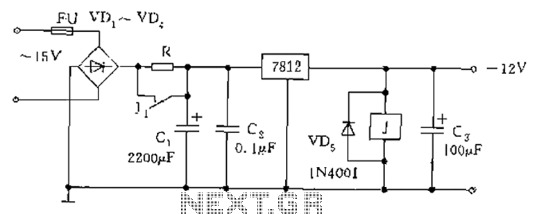
The figure below illustrates the use of a relay in the starting circuit. The power input connects through a resistor R, which serves two purposes: first, it prevents a large current from the capacitor C1 from affecting the power...
This circuit requires a control current that is 100 times smaller than that required by standard optically isolated solid-state relays. It is particularly suitable for battery-powered systems. By utilizing a combination of a high-current TRIAC and a very sensitive...
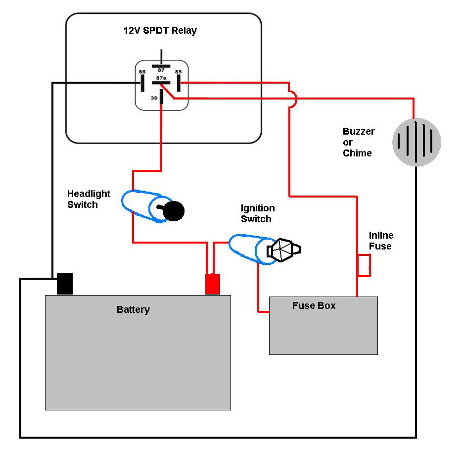
A bike equipped with a 35-watt HS1 bulb is being upgraded to a brighter headlight using an H4 60/65-watt xenon bulb. An expert recommended using relays due to the increased power requirements of the new bulb. Research conducted on...
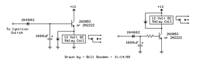
The two circuits illustrated show the operation of opening a relay contact shortly after the ignition or light switch is turned off. A capacitor is charged, and the relay remains closed until the voltage at the diode anode rises...
JG series of photoelectric relay circuit. To ensure reliable operation, a Schmitt trigger circuit has been incorporated. These circuits function similarly; when light strikes the photosensitive component, its internal resistance decreases, activating the transistor VT and subsequently energizing the...
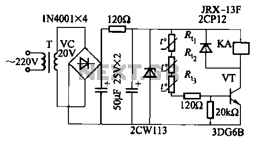
The semiconductor thermistor is an embedded thermal protection element that is sensitive to temperature, with a temperature error of 5. It is reliable, compact in size (diameter of 3.5 mm), and easy to install and embed in windings, making...