Door ajar alarm circuit

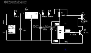
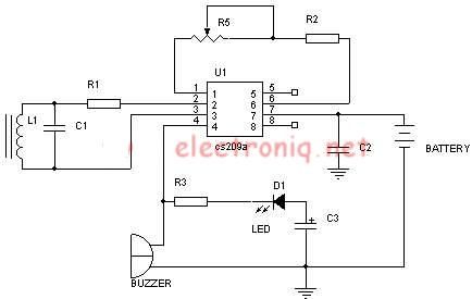
Have you ever accidentally left your front door ajar and had a pet escape? This circuit offers a smart solution to this problem. It is relatively simple yet serves as an excellent example.
The circuit designed to prevent pets from escaping through an open door can utilize a combination of sensors and actuators to provide a reliable solution. The primary component of this system is a magnetic door sensor, which detects whether the door is closed or ajar. This sensor can be mounted on the door frame and the door itself, creating a closed circuit when the door is shut.
When the door opens, the magnetic sensor breaks the circuit, triggering a microcontroller that processes the sensor's output. The microcontroller can be programmed to perform various actions when it detects that the door is ajar. For instance, it can activate a warning alarm or send a notification to a connected smartphone via Bluetooth or Wi-Fi.
To enhance the functionality, an additional component, such as a servo motor or an electronic lock, can be integrated into the system. The servo motor can be used to automatically close the door if it remains open for a predetermined duration, while an electronic lock can secure the door when it is not in use, preventing pets from escaping.
Power supply considerations are crucial for this circuit. A battery-operated solution could be employed for ease of installation and maintenance, while a wired solution could ensure a constant power supply. Furthermore, incorporating a low-power microcontroller can extend battery life significantly.
In summary, this smart door monitoring circuit combines sensors, microcontrollers, and actuators to create a comprehensive solution for preventing pets from escaping through an open door. The simplicity of the circuit design allows for easy implementation, while its functionality can be tailored to meet specific needs.Ever accidentally left your front door ajar and had a pet escape? Here is a smart solution to this problem. The circuit is fairly simple but a great exampl. 🔗 External reference
