
H-bridge of 40N60 mini-brick IGBTs

This DRSSTC (Dual Resonant Solid State Tesla Coil) design showcases a blend of innovation and adaptation from previous models, emphasizing the importance of feedback mechanisms for optimal performance. The use of a JK flip-flop is a critical enhancement, ensuring that the gate drivers are not accidentally disabled during high current RF cycles, which could lead to damage. The implementation of soft-switching is essential in managing the substantial currents that flow through the primary circuit, protecting the IGBTs from thermal stress and potential failure.
The construction of the GDT (Gate Drive Transformer) with Cat-5 networking cable demonstrates a practical approach to achieving high coupling efficiency. The choice of materials, including the copper-clad substrate for the H-bridge, reflects a focus on maximizing surface area for current handling, which is vital in high-power applications like DRSSTCs. The capacitors used in the voltage doubler circuit play a significant role in voltage regulation and energy storage, crucial for maintaining the performance of the coil.
The ongoing modifications to the coil, including adjustments to capacitance and inductance, highlight the iterative nature of the design process in high-voltage applications. The exploration of different configurations and components is indicative of a commitment to optimizing performance and efficiency. The recorded data from recent tests serves as a valuable resource for understanding the relationship between input power and operational efficiency, guiding future iterations of the design. The visual documentation of spark generation and component failures provides insight into the operational limits and challenges faced in the development of high-energy Tesla coils.This first DRSSTC of mine evolved from the ISSTC work I had been doing at the time. Talking with Jimmy Hynes, who built the first DRSSTC, I decided I would give it a try, though with some changes from his design. Jimmy`s DRSSTC used an oscillator to generate the high frequency signal that drives the coil (about 66khz for his coil, I believe).
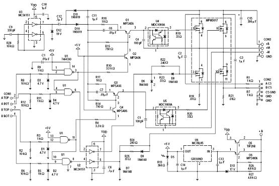
Sinc e I`m not a big fan of using VCOs to tune tesla coils, I would use feedback from the secondary coil itself, ensuring that my driver was always in tune. I would then have to tune the primary circuit to this operating frequency. My feedback design started out very simple, and is seen below: The first schematic was what I originally used for my DRSSTCs.
The second schematic is just a standard H-bridge, nothing too special there. I eventually made an important change to this very basic controller. The change was the addition of a JK flip flop, which would synchronize the interrupter turn off to the feedback zero crossing. This is important because with out this, the interrupter can disable the gate drivers during an RF half-cycle, where current could be very high.
DRSSTCs rely on soft-switching, due to the resonant load. We try to avoid hard switching the several hundreds of amps that may be flowing through the primary circuit, as this is very hard on the IGBTs. Anyway, the flip flop ensures that this should not happen. Below is the schematic (updated 3/17/05): I still use the same basic schematic for the H-bridge, except now I use a voltage doubler at 140VAC, using a pair of 22000uf 200VDC electrolytic capacitors.
These capacitors are much larger than needed, but they are what I had on hand. Here is how I make my GDTs. I take some cat-5 networking cable, and wrap 10 turns of it around a ferrite core. I then parallel all of the "white" conductors, and then series up pairs of the "color" conductors. This gives 2 outputs, and a 1:2:2 transformer with very high primary to secondary coupling. Here is my current H-bridge. It is made from copper clad, etched by hand with my dremel rotary tool. Both sides of the clad are used in parallel to increase conductor surface area. Here are some older spark photos. Some sparks were as long as 55" in length. Notice in one pic, the blue illumination of the background. I caught an IGBT failure on camera, and that blue light is from the fuse exploding violently! 12/18/04: This project is actually still under construction. This is why there are not many construction pictures. because the coil has had many changes made to it. What brought about this construction Well, my desire to try new things. Recently I have been curious to try a lower tank impedance (Z=sqrt(L/C). So I quadrupled my tank capacitance to. 3uF, and reduced my primary to 4 turns. Additionally, I built a new, 6. 5" OD secondary using 26awg, the whole thing runs at around 130khz. Here is the new control board I etched for this coil. Notice how I stacked the gate drivers. This is ok in a pulsed application like this, where driver heating is not considerable. You must not do this in a CW system! I ran the new setup (6. 5"x22" secondary, . 3uf MMC) in the garage yesterday and recorded some data. The % of VAC is of 140VAC input which is then doubled to 400VDC max. Power into the coil was recorded at the power outlet. Notice how poor the efficiency is as the ON period increases! 🔗 External reference
Related Circuits
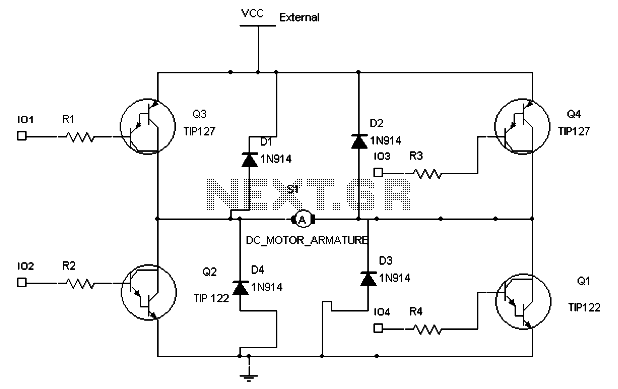
The following circuit illustrates an N-Channel H-bridge motor drive circuit diagram. Features include low voltage motor drives utilizing N-channel MOSFETs. The N-Channel H-bridge motor drive circuit is designed to control the direction and speed of a DC motor using low...
A very popular circuit for driving DC motors (ordinary or gearhead) is called an H-bridge. It's called that because it looks like the capital letter 'H' on classic schematics. The great ability of an H-bridge circuit is that the...
A schematic for an H-bridge circuit is required to convert a 350V DC input into a 230V AC output at a frequency of 50Hz. The design should utilize a 555 timer integrated circuit (IC) along with MOSFETs. An H-bridge is...
An H-bridge circuit has been developed utilizing four floating gate drivers and four insulated gate bipolar transistors (IGBTs). The attached schematic illustrates one half of the H-bridge configuration. The circuit operates effectively, but there are additional considerations to address. The...
To maintain a constant speed of the motor under varying load conditions, a control application circuit is required. An H-Bridge circuit can be utilized to manage both the speed and direction of the motor. The accompanying diagram illustrates the...
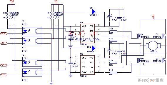
The drive circuit for the electromotor comprises a FET bridge circuit, a FET base drive circuit, a current sensor for the motor drive circuit, and a relay. The FET bridge circuit primarily consists of four high-power MOSFETs, which must...