
Lead Acid Battery Charger #2

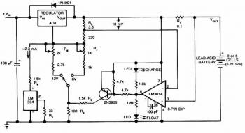
This circuit operates as a constant current source with an integrated current limiting feature. The primary component, Q1, is a transistor that controls the output based on the current flowing through the circuit. Resistors R1 and R4 play critical roles in setting the current limit and ensuring stable operation. The calculated output voltage is contingent upon the values of P1, R2, and R3, which are essential for adjusting the output characteristics. For applications requiring fast charging, the circuit is designed to provide a specific voltage that corresponds to the battery configuration, ensuring compatibility with various battery types.
The use of a trimmer potentiometer (P1) allows for fine-tuning of the output voltage, providing flexibility in applications where precise voltage levels are necessary. The requirement for the input voltage to exceed the output voltage by at least 3 V is a crucial design consideration, as it ensures the LM317 regulator operates within its specified range, preventing dropout conditions that could lead to inefficiencies or operational failures.
Thermal management is paramount, especially for the LM317, which dissipates heat during operation. A large heat sink is recommended to maintain optimal operating temperatures and prevent thermal shutdown. The choice of Q1 is also significant; while the BC140 is a suitable option, alternatives such as the NTE128 or ECG128 can be employed without compromising performance, allowing for greater flexibility in component sourcing.
Overall, this circuit is versatile, functioning effectively as both a battery charger and a general-purpose power supply, making it suitable for a wide range of electronic applications. Its design emphasizes reliability, efficiency, and adaptability, catering to various voltage and current requirements.The above pictured schematic diagram is just a standard constant current model with a added current limiter, consisting of Q1, R1, and R4. The moment too much current is flowing biases Q1 and drops the output voltage. The output voltage is: 1. 2 x (P1+R2+R3)/R3 volt. Current limiting kicks in when the current is about 0. 6/R1 amp. For a 6-volt batte ry which requires fast-charging, the charge voltage is 3 x 2. 45 = 7. 35 V. (3 cells at 2. 45v per cell). So the total value for R2 + P1 is then about 585 ohm. For a 12 V battery the value for R2 + P1 is then about 1290 ohm. For this power supply to work efficiently, the input voltage has to be a minimum of 3V higher than the output voltage. P1 is a standard trimmer potentiometer of sufficient watt for your application. The LM317 must be cooled on a sufficient (large) coolrib. Q1 (BC140) can be replaced with a NTE128 or the older ECG128 (same company). Except as a charger, this circuit can also be used as a regular power supply. 🔗 External reference
Related Circuits
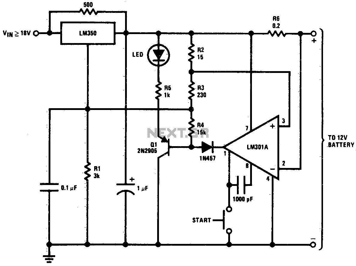
This circuit is a high-performance charger for gelled electrolyte lead-acid batteries. The charger quickly recharges the battery and automatically shuts off when it reaches full charge. Initially, the charging current is limited to 2A. As the battery voltage rises,...
Bidirectional control is implemented for a motor to increase its operational degree. The motor can rotate in either direction with a current of 1A. A variable duty cycle multivibrator is utilized to achieve the construction and control of the...
This circuit provides an initial voltage of 2.5 V per cell at 25°C to quickly charge the battery. As the battery charges, the charging current decreases, and when it drops to 180 mA, the charging circuit reduces the output...
The circuit safeguards a solid-state relay from overload conditions. It limits current, automatically disconnects the load upon detecting a short circuit, and generates a fault-condition output signal. During normal operation, the controlling pulse train generator (ptP) sets the flip-flop,...
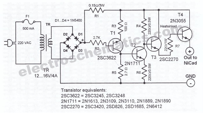
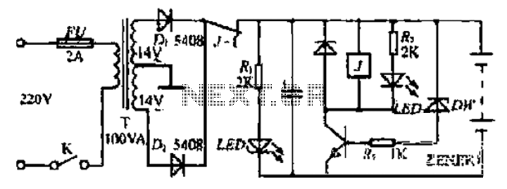
This NiCd battery charger circuit schematic can charge 6 volts as well as 12 volts NiCad batteries. It uses a transformer that can deliver 4 to 5 A current. The NiCd battery charger circuit is designed to accommodate both 6V...
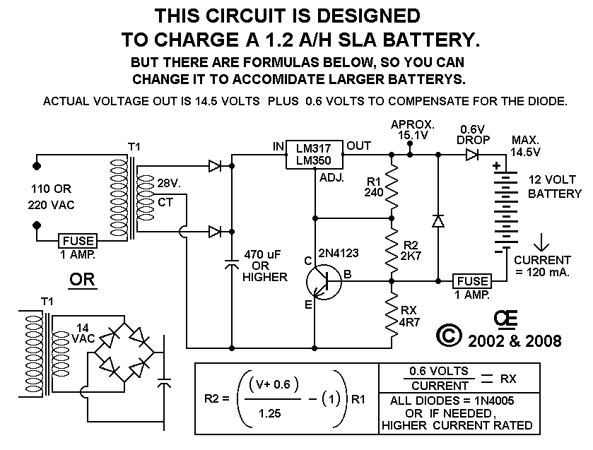
This circuit provides effective charging results for Gel Cell or Sealed Lead Acid (SLA) type batteries, which are utilized in metal detector projects. It can be modified to accommodate higher current batteries and is likely suitable for batteries with...