
Schematic Diagram FM Transmitter 4Watt

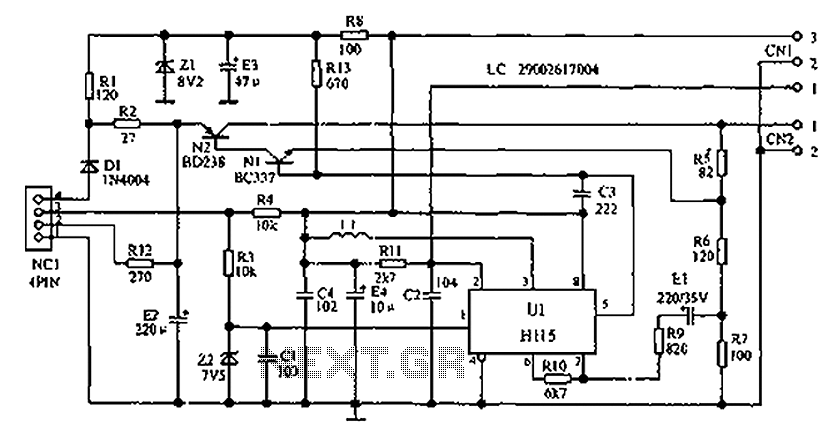
The circuit described involves an L2 RFC (Radio Frequency Choke) with a resistance of 1MΩ, which is crucial for filtering unwanted frequencies and ensuring that only the desired signals are amplified. The inductor is wound with a sufficient number of coils using fine insulated wire, which enhances its inductance and allows for effective energy storage in the magnetic field when current flows through it. The arrangement creates a parallel L-R circuit, where the inductor (L) and the resistor (R) are connected in parallel, enabling the circuit to manage energy dissipation while maintaining the desired frequency response.
The addition of capacitors C7 and C8 plays a vital role in tuning the circuit. These capacitors are used to adjust the overall impedance of the aerial system, allowing for fine-tuning of the circuit to maximize the clarity and strength of the transmitted voice signal. By manipulating their values, the resonance of the circuit can be optimized to ensure that the audio signal is transmitted effectively, reducing noise and enhancing the quality of the received signal. This setup is particularly useful in radio communication applications, where clarity and fidelity of voice transmission are paramount.
In summary, this circuit configuration, with its combination of a high-value resistor, an inductor, and tuning capacitors, is designed to enhance radio frequency performance, ensuring that voice signals are transmitted and received with optimal clarity.L2 RFC (resistance 1MOhm with wrapped around her inductor of enough coils from fine isolated wire. Scratch of utmost inductor and you stick in utmost the resistance making thus a parallel L-r circuit. ) With their C7, C8 we adapt the resistance of aerial (practically to them we regulate so that it is heard our voice in the radio as long as you beco
me cleaner). 🔗 External reference
Related Circuits
The following describes the circuits of a minibus odometer, which integrates electronic and mechanical components to form a new type of instrument for measuring distance and speed. Pulse signals are generated by the locomotive speed detection system and transmitted...
RF Wireless Data Transfer communication circuit diagram. A wireless communication interface was implemented to facilitate data transfer from one point to another using RF technology. The RF Wireless Data Transfer communication circuit utilizes radio frequency (RF) technology to establish a...
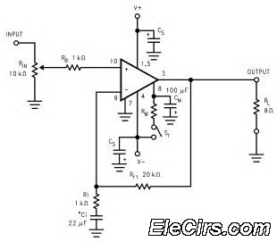
The LM3886 high-performance audio power amplifier circuit schematic is a crucial component in sound reproduction within audio systems. This audio power amplifier utilizes the LM3886 integrated circuit to enhance sound quality and output. The LM3886 is a high-performance audio power...
This circuit is sourced from a remote control tarantula transmitter that operates at a frequency of 49.86 MHz. The schematic is also available on the FCC website by searching for the FCC ID. This device complies with Part 15.235...
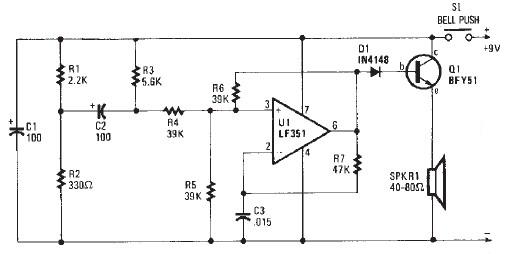
This electronic door buzzer circuit schematic has a straightforward function and is simple to construct. The circuit employs an LF351 operational amplifier along with a few common electronic components. When the S1 push-button is pressed, a positive voltage is...
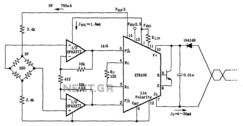
The XTR106, as illustrated in the figure, features two internal source voltages of 2.5V and 5V, enabling it to accommodate a wide range of bridge values without the need for additional circuitry. It can operate with bridge resistances lower...