
static detector negative ion detector

The static electricity detector circuit primarily consists of a single Field Effect Transistor (FET), which serves as the sensitive element for detecting electric fields. The design emphasizes the high input impedance characteristic of FETs, allowing it to detect minute changes in voltage induced by static electricity or negative ions. The probe, made from a short length of bare copper wire, is critical for sensing electric fields; it is connected directly to the gate terminal of the FET, which remains open-circuit to maximize sensitivity.
Construction of the circuit should follow an open layout rather than being mounted on a veroboard or PCB. This is essential because traditional circuit boards can introduce parasitic capacitance, effectively lowering the input impedance and compromising the detector's performance. Components should be soldered directly together with minimal distance between them to maintain high sensitivity.
The meter used for output readings should be a center-zero type to accommodate both positive and negative charges. The choice of 1 mA or 250 µA for full-scale deflection allows for flexibility depending on the application and desired sensitivity. Calibration involves using a multimeter to set the voltage at the FET drain to zero before replacing the meter, ensuring accurate readings without mechanical stress on the meter's needle.
In practical applications, the detector can be used to monitor environmental static charges or the output of ionizers. The response of the circuit to nearby electronic devices, such as televisions, can be tested to evaluate its effectiveness. The detector's ability to indicate changes in charge makes it a valuable tool for assessing electrostatic conditions in various settings, including laboratories and clean rooms.A sensitive detector for static electricity based around a single Field Effect Transistor It can also be used to detect the presence of negative ions, or test a negative ion generator. This circuit utilizes the extra high input impedance of a FET, and also demonstrates the gate terminals sensitivity to changes in voltage.
The gate terminal here is left open circuit, connected only to the "probe". The probe is just a few inches of bare copper wire. With no fixed DC biasing, the gate terminal will respond to micro changes in voltage. This causes a current change in the drain circuit and the meter will indicate a charge or "field strength". It is important not to make this circuit on veroboard or PCB material as this will reduce the effective gate impedance.
Instead use an "open" construction technique soldering each component together. The probe should not be touched directly and is best insulated in a plastic pen sleeve. As static electricity can have either a positive or negative charge, the meter used should be a centre zero type. Full scale deflection can be 1mA or 250uA for greater sensitivity. Remove the meter and use a multimeter to measure the voltage between FET drain and the preset resistor.
Adjust the preset for 0 volts and then replace the meter. This will avoid "bending" the needle. If placed in a room the meter will detect changes in static charge, positive charge deflecting the needle one way and negative the other way. You can test the circuit by placing the unit say 5 feet away from a TV set. When switched on, the meter needle should jump to full scale deflection and then drop down again. If you have a room ionizer, its output can be monitored by moving the probe in front of it. As the detector responds to changes in charge, you may need to move the detector around to see the effect, but it will prove the output from an air ionizer is working.
🔗 External reference
Related Circuits
This circuit is designed to detect whether the load of a battery charger or plug-in adapter is properly connected. The load may consist of a set of batteries needing charging or any other device that operates on low DC...

RS-232C serial port lines are quite prone to be damaged by overvoltages. The damage to computer serial ports has become more and more expensive to replace because of higher integration: usually, you have to buy a new motherboard if...
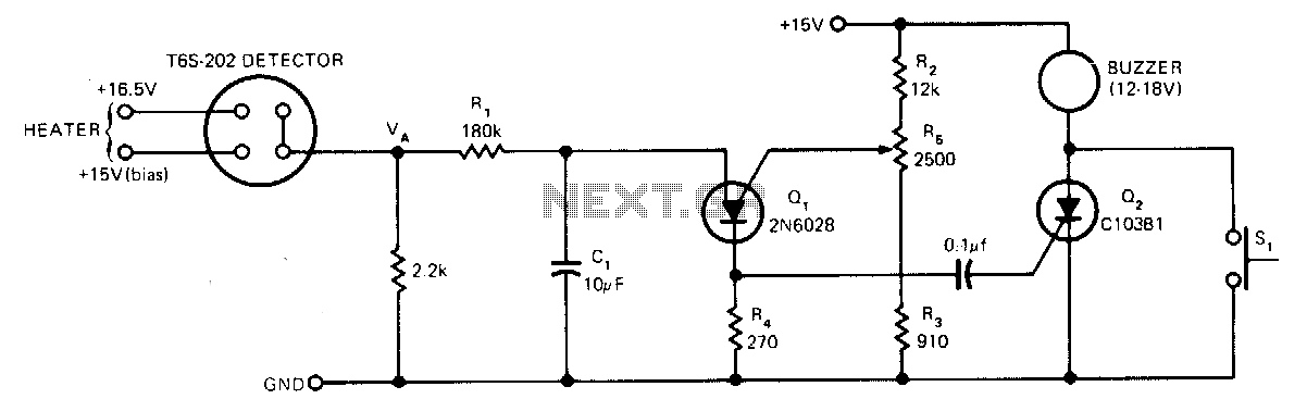
The sensor operates based on the selective absorption of hydrocarbons by an n-type metal-oxide surface. The device features a heater designed to eliminate hydrocarbons once smoke or gas is no longer detected in the immediate vicinity, allowing for reuse....
Variable resistor R1 adjusts the light threshold at which the circuit triggers. R1's value is chosen to match the photocell's resistance at darkness. The circuit uses a CMOS 4001 IC. Gate U1a acts as the trigger, U1b and c...

Compared to other operational amplifiers, the OP90 has a significant advantage in low power consumption. Its low power requirements allow for a wide range of power supply voltages (from 1.6V to 18V, and it can also operate with dual...
A newcomer to the forum is seeking assistance with DIY electronic circuits and lacks a formal background in electrical engineering. The inquiry indicates a desire to learn and engage with the community on topics related to DIY electronic circuits. For...