Resistors Calculator Inverting Op-Amp
This calculator determines the bias and feedback resistors for an op-amp, given the gain and desired output bias point.
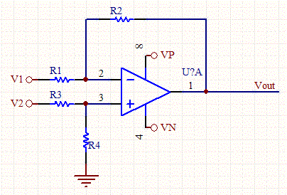
An inverting amplifier is a special case of the differential amplifier in which that circuit's non-inverting input V2 is grounded, and inverting input V1 is identified with Vin above. The closed-loop gain is Rf / Rin, hence

The simplified circuit above is like the differential amplifier in the limit of R2 and Rg very small. In this case, though, the circuit will be susceptible to input bias current drift because of the mismatch between Rf and Rin.
To intuitively see the gain equation above, calculate the current in Rin:

then recall that this same current must be passing through Rf, therefore (because V- = V+ = 0):

There are many free parameters to the design so enter the value of R1, which will scale the other resistors. Use V1 as the input for the inverting Op-Amp, and V2 as a voltage offset if needed. Set V2 to zero if no offset is required.

