Resistors Calculator Non Inverting Op-Amp
This calculator calculates the bias and feedback resistors for a non-inverting op-amp, given the gain and desired output bias point. First determine the desired gain of the ac signal and the quiescent output voltage witch is the value when the AC input signal is zero.
The input impedance of the simplified non-inverting amplifier is high, of order (the op amp's input impedance) × (open-loop voltage gain of the op amp) times the closed-loop gain.
In the case of the ideal op amp, with (open-loop voltage gain of the op amp) infinite and (the op amp's input impedance) infinite, the input impedance is infinite. In this case, though, the circuit will be susceptible to input bias current drift because of the mismatch between the impedances driving the V+ and V- op amp inputs.
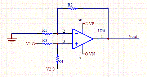
Choose the value of R1 that will scale the other two resistors. V1 is the input voltage for the inverting Op-Amp, V2 is the voltage offset if its needed and set V2 to zero if no offset is required.
A non-inverting amplifier is a special case of the differential amplifier in which that circuit's inverting input V1 is grounded, and non-inverting input V2 is identified with Vin above, with Rg » R2. Referring to the circuit immediately above,
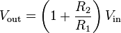
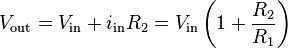
To intuitively see this gain equation, use the virtual ground technique to calculate the current in resistor R1:

then recall that this same current must be passing through R2, therefore:
A mechanical analogy is a class-2 lever, with one terminal of R1 as the fulcrum, at ground potential. Vin is at a length R1 from the fulcrum; Vout is at a length R2 further along. When Vin ascends "above ground", the output Vout rises proportionately with the lever.

RF based Automatic meter reading, or AMR, is the technology of automatically collecting data from...

Using this circuit will give Good Charging results to a Sealed Lead Acid Battery, like I use in...

Three lights are controlled by the three channels. One light will pulse in response to the bass,...

This circuit is a 555 timer IC connected as a square-wave generator. Its base frequency is...

This circuit adds a VLF AM component to an audio signal. This effect is widely used in musical...

Many low pass filter circuits for subwoofer seem to be given And this is also just Another one....

This tutorial is in continuation with previous tutorials on 8051 Assembly Programming. Now we...

This is a very excellent 40W power amplifier design using TDA2030 IC and two transistors. The...

There are not many AM transmitters that are easier to build than this one because the inductor is...

Two KOSS A-1220 headphone amps. Each share the same model number, yet have completely different...

In the original circuit, a three-diode string was wired in series to R10. Two of these diodes are...

The schematic for this project really only consists of adding a single 5mm LED to one digital...

1500A-7V-phase thyristor power regulator circuit a plating It consists of the main circuit,...

Circuit shown in Figure 3-80. Which controls part of the transistor multivibrator. Multivibrator...

Circuit works The liquid level automatic controller circuit from the power circuit, a level...